Assembly
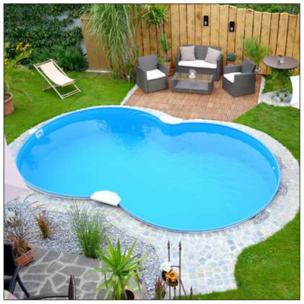
Assembling the figure-of-eight pool – step by step
Here you will find the manufacturer's complete instructions for the assembly and use of figure-of-eight steel pools (MTH): from preparing the base and the excavation, through assembling the wall, the liner and the built-in elements, to backfilling with lean concrete, maintenance, winterising and safety notes. The steps are valid only for figure-of-eight pools.
1Important notes
First read these complete instructions carefully in all their points and observe all the notes. The images and graphics in the instructions are partly symbolic and indicative and serve for general illustration.
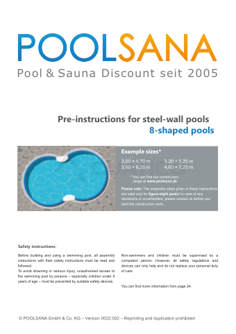
Dimensions of figure-of-8 pools:
- 3,00 × 4,70 m
- 3,20 × 5,25 m
- 3,60 × 6,25 m
- 4,60 × 7,25 m
The assembly steps described in these instructions are valid only for figure-of-eight pools.
Before you start assembly, check that your pool is complete. Check that all parts are in perfect condition.
Make sure that only suitable building materials come into contact with the steel wall. For example, if silicone is used, it must be acid-free, as otherwise the protective coating of the steel wall is damaged and rust may appear. If necessary, the suitability of the material for the intended purpose must be checked beforehand.
1.1Earthing of the pool
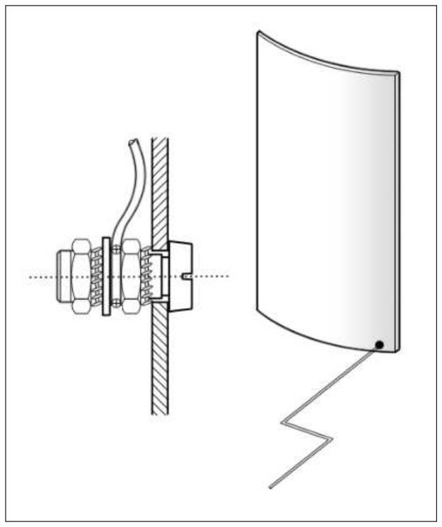
The pool and all large metal parts must be connected to the equipotential bonding, in accordance with the regulations, by an authorised electrical contractor.
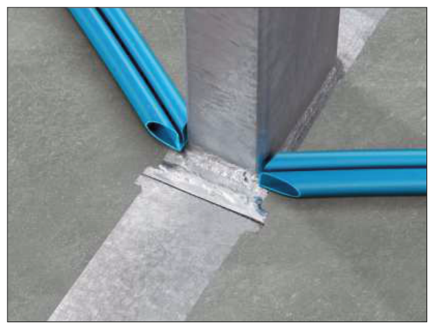
For this you can drill the steel wall at its lower part (afterwards seal it again with zinc spray or plastic paint) and fasten an earthing cable to a metal screw (see Fig. 2). From there the cable is led to an earth rod.
All electrical work must be carried out by a recognised specialist company, in accordance with the applicable DIN and VDE standards (e.g. DIN VDE 0100 part 702).
2.1Parts of the pool
- Joining profile for the steel wall
- Liner
- Steel wall
- Covering platform (seat)
- Top edge sections
- Main beam
- Side post
- Plastic bottom profile sections
The individual components may differ in appearance without this affecting their function (see Fig. 3).
2.2Location for the pool
The pool should be, as far as possible, in the sun and not too far from the house. The skimmer (the surface skimmer) should be placed in the direction of the prevailing wind, so that the dirt on the water surface is driven towards it. However, it is more important that the skimmer is installed on the side closest to the filtration system.
2.3Location for the filtration system
In principle, the filtration system should be located as close as possible to the pool, and it is more convenient for the suction pipe (the pipe to the skimmer) to be shorter than the delivery pipe (the pipe to the inlets).
The filtration system can be placed, as you choose, in a chamber, in the house or in a garden shed, etc. In the house and in the chamber a floor drain must be provided for possible water leaks. The backwash water must also be drained away: on average about 200 l every 1–2 weeks. This can be done through a fixed connection to the sewer or, if necessary, with a hose directed to a suitable drain.
If the filtration system is higher than the water level, a non-return valve must as a rule be fitted on the suction side, that is, in the pipe to the skimmer. It is installed at a distance of 1.00–1.50 m from the sand filter and must be accessible at all times.
When choosing the location of the filtration system, the planned heating method also plays a role. If the pool will be heated with a system of solar absorbers for pools, the filtration system should be installed, as far as possible, close to the place of the solar absorbers. And if an air-to-water heat pump that is installed outdoors is planned, it is recommended to place the filtration system in the garden as well. On the other hand, when connecting a heat exchanger to the central heating, placing the filter in the house is almost unavoidable.
2.4Installation variants
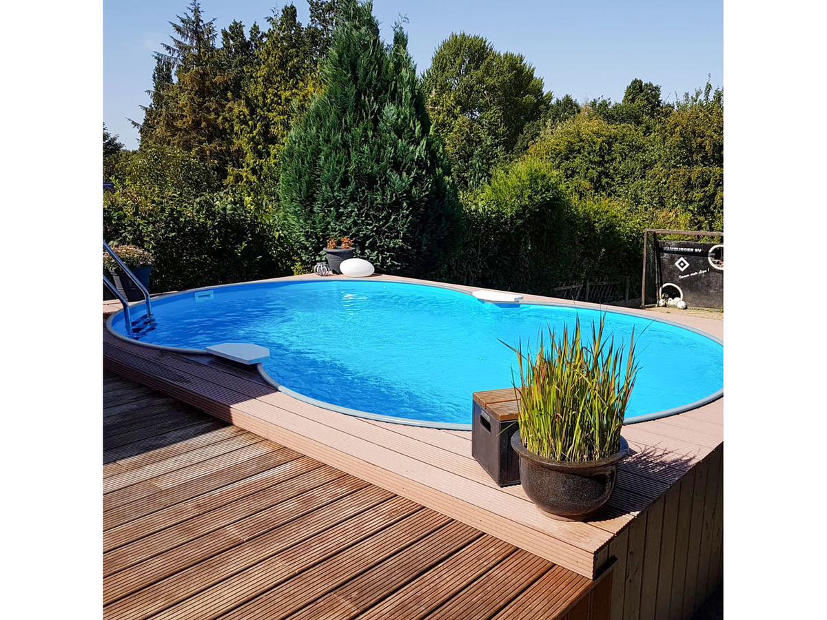
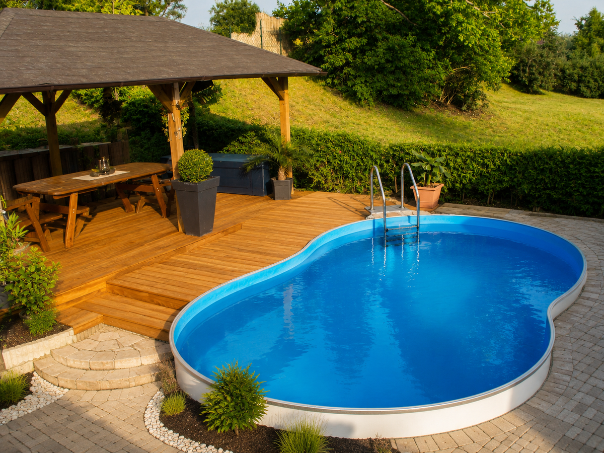
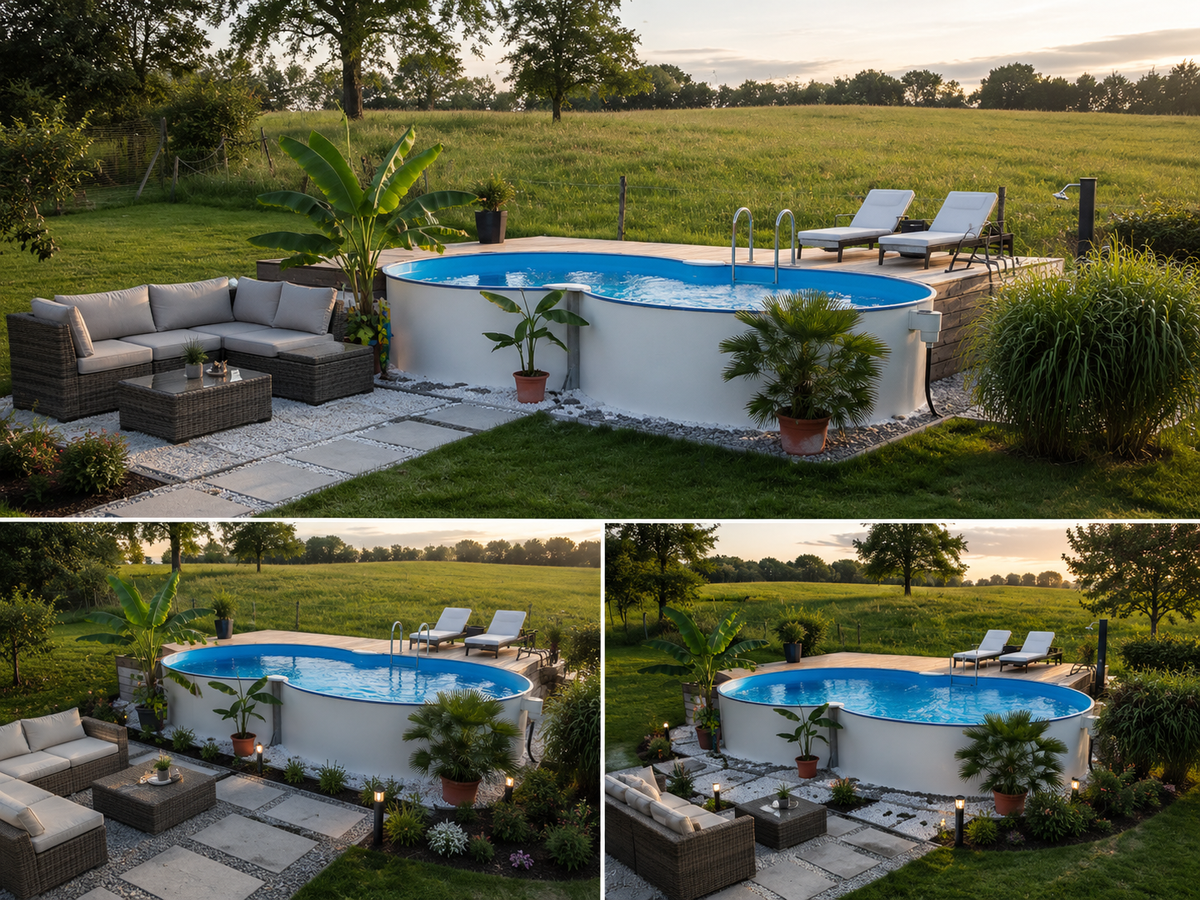
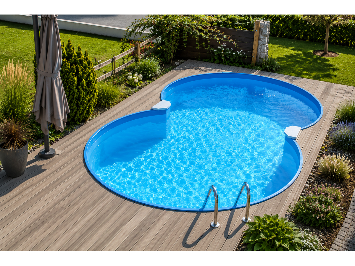
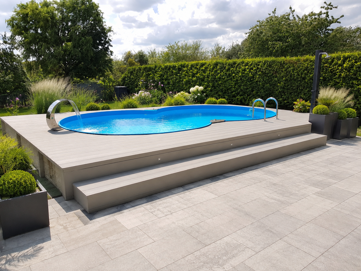
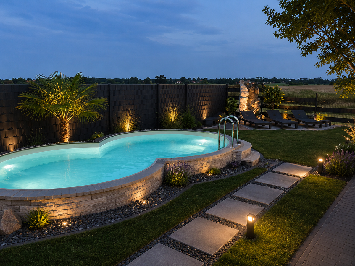
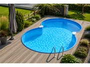
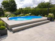
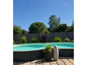
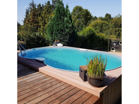
Different types of installation are possible for a figure-of-eight pool (see Fig. 4, 5 and 6):
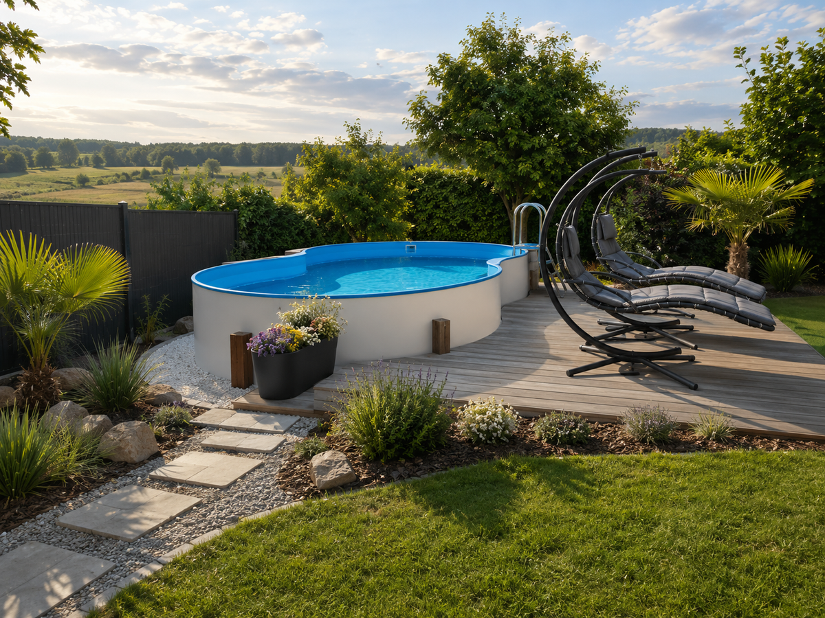
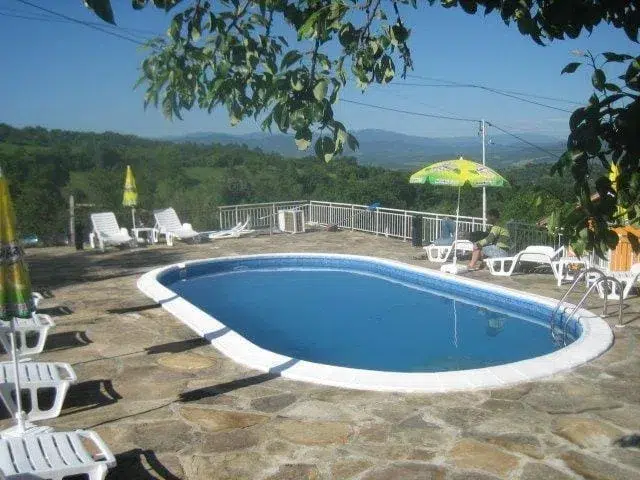
- In-ground pool – possible with all pool depths. In-ground pools must be backfilled completely behind with lean concrete.
- Partially buried pool – this installation variant is also possible with all pool depths. A pool 150 cm high must be buried at least 50 cm in the ground. The backfill behind the buried part must be made with lean concrete.
- Free-standing pool – possible only for pools 120 cm and 135 cm high.
2.5Preparing the base
The site for the pool must meet the static requirements and be completely level, so any slopes must be excavated.
Never build embankments on hillsides! Slopes must be reinforced with a retaining wall. Under no circumstances may the pool wall hold back the hillside!
The ground under the pool must be natural, not fill. Fill soils must be compacted so that the pool does not sink, or else more effort must go into the base. In case of doubt consult a building specialist or a structural engineer.
Important when burying: bear in mind that the pool must under no circumstances be in the groundwater zone. If groundwater appears already when excavating to the corresponding depth, it is essential to consult a building specialist and find a solution.
A reinforced concrete slab (strength class C25/30) is needed as a base and, underneath, as a rule, a base layer or compacted gravel. For in-ground pools a drainage pipe is generally recommended.
2.6Inner liner of the pool
The inner PVC liner of the pool is made of thermoplastic material. That is why you should make sure to install the pool at an outside temperature of roughly between +15 °C and +25 °C. Do not hang the inner liner in strong sunlight either; in that case wait until evening for the installation.
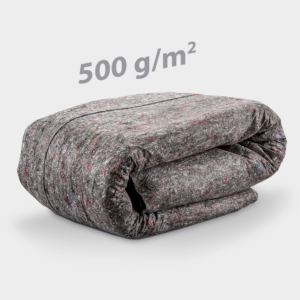
Be sure that the inner PVC liner comes into contact only with material compatible with PVC. That is why we generally recommend a base of protective polyester fleece (normally included in complete pool kits).
3.1Plan and dimensions
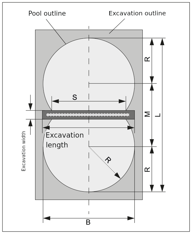
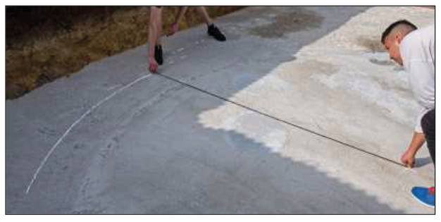
First mark the outline of the pool on the ground. The semicircles of the curves are most easily marked with a string passed around a nail driven in at the centre of the diameter.
- B = width of the pool
- L = length of the pool
- R = radius of the pool
- S = distance between the posts
- M = distance of the fixing points for marking the semicircles
Values according to the pool size (B × L):
- 3,00 × 4,70 m: R = 1,50 m; S = 2,50 m; M = 1,70 m
- 3,20 × 5,25 m: R = 1,60 m; S = 2,50 m; M = 2,05 m
- 3,60 × 6,25 m: R = 1,80 m; S = 2,50 m; M = 2,65 m
- 4,60 × 7,25 m: R = 2,30 m; S = 3,80 m; M = 2,65 m
3.2Excavation
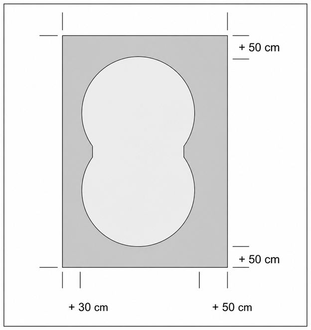
If the pool is buried completely, a working space of at least 50 cm must be provided when excavating on the end side where the skimmer is. If 2 return inlets located on the opposite end side are used, a working space of 50 cm for the pipes must also be provided on that side, as well as on one of the two long sides. Otherwise a distance of 30 cm is sufficient.
If the pool is buried at most up to halfway and the pipes are laid on the ground, a distance of 30 cm on all sides is sufficient, regardless of the number and arrangement of the built-in elements.
It must already be pointed out here that the later backfill directly behind the steel walls must be made with lean concrete 15–30 cm thick; you will find more information below, in section 5.
Pool with 2 inlets (see Fig. 8):
Recommended excavation dimensions (width × length):
- Pool 3.00 × 4.70 m: excavation 3.80 × 5.70 m
- Pool 3.20 × 5.25 m: excavation 4.00 × 6.25 m
- Pool 3.60 × 6.25 m: excavation 4.40 × 7.25 m
- Pool 4.60 × 7.25 m: excavation 5.40 × 8.25 m
To keep things simple, the building pit is usually dug rectangular. Of course, it can also be dug following the outline of the pool (with the appropriate distance).
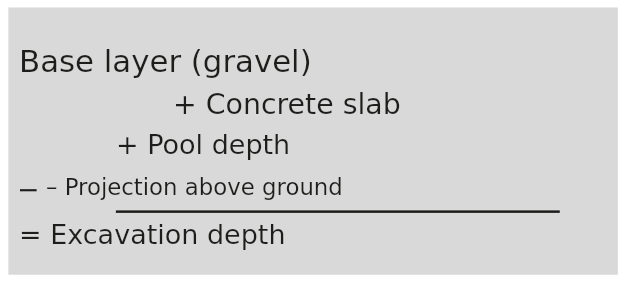
The depth of the building pit depends on the thickness of the concrete slab and of the base layer (compacted gravel), as well as on the depth of the pool and on the height at which the pool protrudes from the ground. The formula is:
The thickness of the concrete slab is, as a rule, 20 cm, and that of the base layer about 15 cm (the exact thickness is determined by the construction company according to the base).
Important: If the filtration system is not directly next to the pool, trenches must also be dug for the pipes to be laid. They should be about 40–50 cm wide and about 100 cm deep. If the pipes can be drained completely before winter by means of drain devices at the lowest point of the pipe, they can be laid higher and sloping towards the drain.
For this it is recommended to provide, at the corresponding place, a large plastic tube or similar with an inside diameter of at least 160 mm.
Likewise, if necessary, trenches must be excavated for the solar pipes (from the filtration system to the solar absorber) and for the electrical cables.
3.3Steel load-bearing structure and concrete slab
When a concrete slab and a base layer are planned, the excavation is usually already deep enough for the steel load-bearing structure. It is recommended to place the support already when pouring the concrete slab. If the structure is installed only afterwards or the thickness of the concrete slab is less than the depth of the support, a trench must be dug.
Trench for the steel support (dimensions in cm; support in L – length × width of the trench):
- Pool depth 120 cm: pool 300 × 470 – trench 330 × 25; pool 320 × 525 – trench 330 × 25; pool 360 × 625 – trench 330 × 25; pool 460 × 725 – trench 460 × 25
- Pool depth 135 / 150 cm: pool 320 × 525 – trench 330 × 28; pool 360 × 625 – trench 330 × 28; pool 460 × 725 – trench 460 × 28 (for the pool 300 × 470 this variant does not exist)
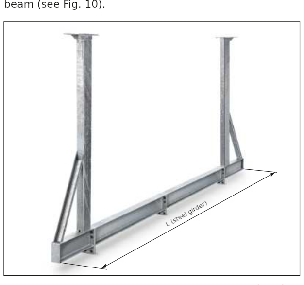
The steel support consists of two side posts of the wall and, depending on the size of the pool, two to three elements of the main beam. The depth of the support is between 14 and 18 cm depending on the size or depth of the pool. Before installation, the whole structure must be carefully bolted together by the end plates.
Tightening torque of the screws: M 12 = 85 Nm; M 16 = 206 Nm.
Place the bolted steel support in the prepared bed, align it horizontally and vertically and fix it. The concrete or the concrete slab must coincide with the upper edge of the main beam (see Fig. 10).
The upper edge of the main beam is level with the upper edge of the concrete slab (Fig. 10: wall post, main beam, concrete slab, base layer, excavation width B).
4Assembling the pool
Depending on its size, the pool must be assembled by 3–4 people on a windless day. When placing the steel wall we recommend wearing gloves.
First mark the outline of the pool on the ground. This is done most easily with a string passed around a nail driven in at the centre of the diameter. Mark the lines with a bricklayer's pencil or chalk.
4.1Placing the bottom profiles
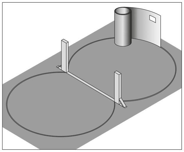
Join the individual sections of the bottom profiles (width about 20 mm) with the connecting tubes and lay the closed outline of the pool on the ground (see Fig. 12 and 13). Follow the marked plan. Check the dimensions and symmetry exactly and, if necessary, shorten 1–2 bottom profiles.
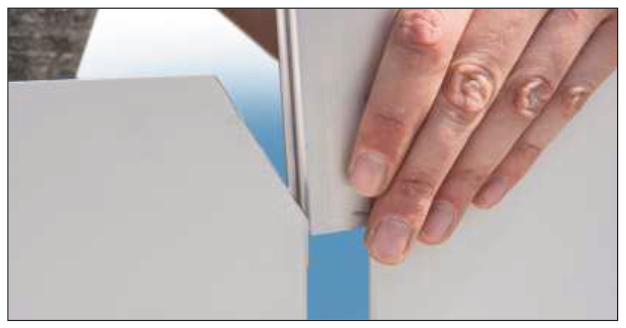
Mitre-cut the bottom profiles that end up on the outside next to the wall post, as shown in Fig. 14.
4.2Placing the steel wall
To get into the pool you will need a ladder for the later assembly. However, later on, when installing the liner, care must be taken to prevent this builder's ladder from damaging the liner.
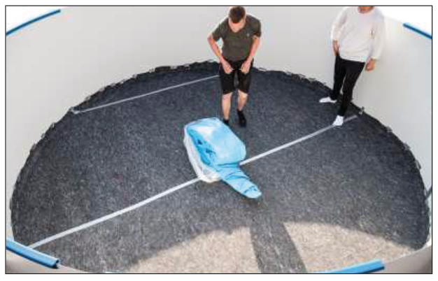
In addition, before assembling the pool wall, place the folded inner liner inside the pool.
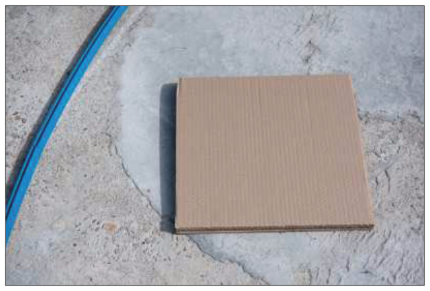
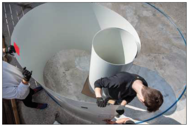
Together with your helpers place the steel wall approximately where the skimmer (the surface skimmer) will be installed later, on sturdy boards and cardboard, so that the steel wall can be pulled more easily when unrolling it (see Fig. 15). Under no circumstances should the steel wall be dragged across the concrete floor when unrolling it, as it could be damaged.
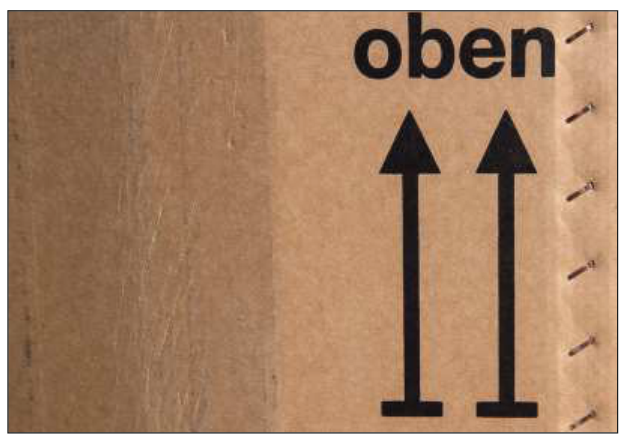
The cardboard with the steel wall usually has “top” or similar written on it (see Fig. 16); it is important to place the steel wall the right way round.
The steel wall is always rolled up at the factory facing inwards, so that the rolled-up steel wall shows the outer face of the pool. Unroll the steel wall in the same direction in which it is rolled up.
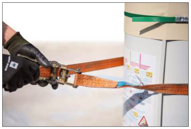
When unrolling and placing the steel wall wear gloves and secure the steel wall with a belt or similar before opening or unrolling it (risk of injury!) (see Fig. 17).
The cut-out for the skimmer is usually at the beginning of the steel wall being unrolled (about 1–2 m from the start); if there are several packages with steel wall, the cardboard boxes state which part of the steel wall and which cut-outs for built-in elements they refer to.
Unroll the steel wall and place it on the corresponding profiles (see Fig. 18). The skimmer cut-out must be at the desired place (if possible close to the filtration system).
If a joining profile is fitted on one side of the steel wall, it must be removed. In larger pools the steel wall is divided into 2 parts, that is, the connection with the joining profile is made twice.
To hold the steel wall temporarily in place, several top edge sections can be fitted during assembly (see Fig. 20).
Also always make sure that the steel wall sits firmly in the bottom profile.
4.3Adjusting the bottom profiles and joining the wall ends with the joining profile
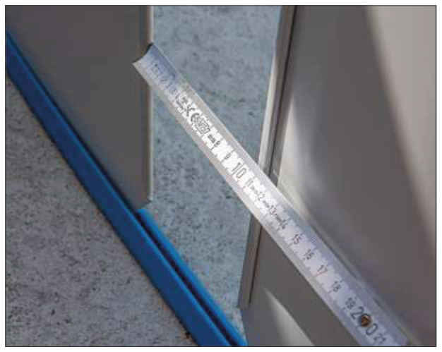
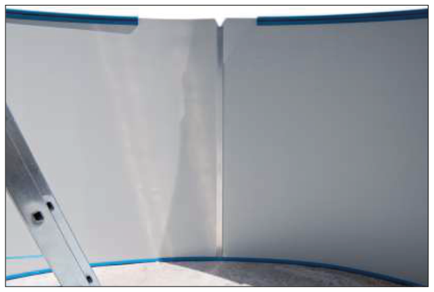
The distance between the ends of the steel wall must be about 5 mm so that the joining profile can connect the two ends of the steel cladding. This must be taken into account when adjusting or shortening the bottom profile.
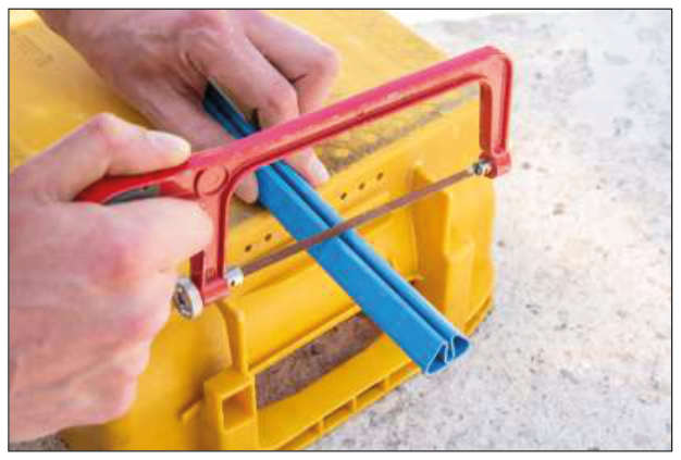
Shortening the bottom profile: unroll the steel wall and measure any overhang of the bottom profile. Then pull the steel wall away again about 50 cm from the bottom profiles and shorten a bottom profile accordingly (take into account the 5 mm distance between the ends of the steel wall for the joining profile; see above).
Then place the whole steel wall in position again and slide the joining profile onto it (see Fig. 23).
Depending on the pool, the joining profile may have one bevelled side. In that case place it so that the bevelled side is on the inside and at the top. If there is no bevel, the upper/lower side does not matter.
With a slight back-and-forth movement when sliding on the joining profile you can improve its mobility. It is easier to slide it on with a rubber mallet. Incorrect sliding and forced blows on the joining profile damage the steel cladding (limitation of the warranty) and worsen the stability of the pool.
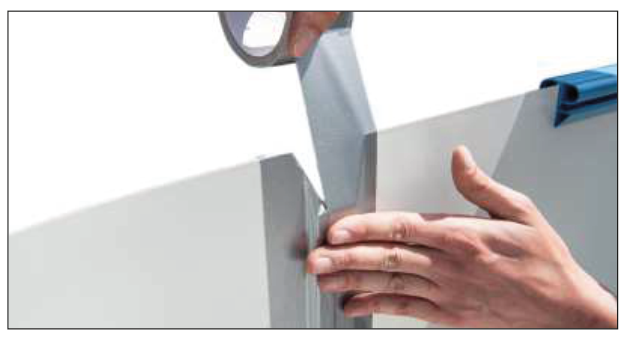
To protect the inner liner from damage, the joining profile must be covered on the inside with adhesive tape (see Fig. 26).
Check that the pool is absolutely level. With height differences of more than 2 cm the manufacturer's warranty is lost. In that case look for the cause and eliminate the problem, e.g. by touching up the base.
4.4Preparing the connection openings
Also follow, if necessary, the corresponding assembly instructions of the manufacturer, if they are enclosed with the built-in elements.
4.4.1Built-in skimmer (surface suction unit)
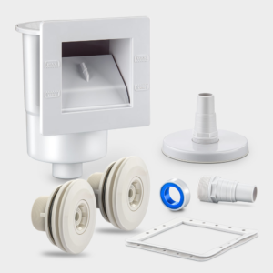
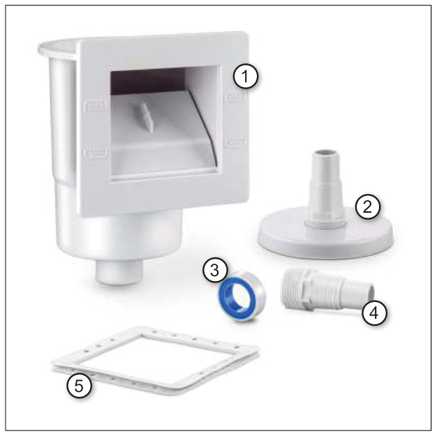
Skimmer parts: 1) skimmer body; 2) suction plate; 3) PTFE (teflon) tape; 4) hose connector; 5) double gasket (see Fig. 27).
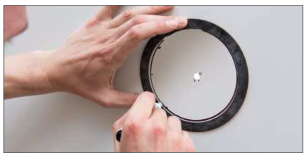
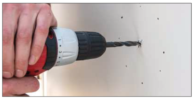
In pool kits and individual pools, the corresponding opening for the skimmer is usually already cut out or pre-punched. If the cut-out is made on site, the skimmer opening and the flange holes are marked and then cut out with a drill and jigsaw or drilled.
The distance between the upper edge of the skimmer opening and the upper edge of the steel wall must be 5 cm. Then carefully remove the burrs from the edges.
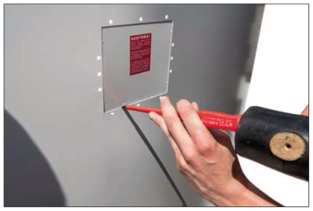
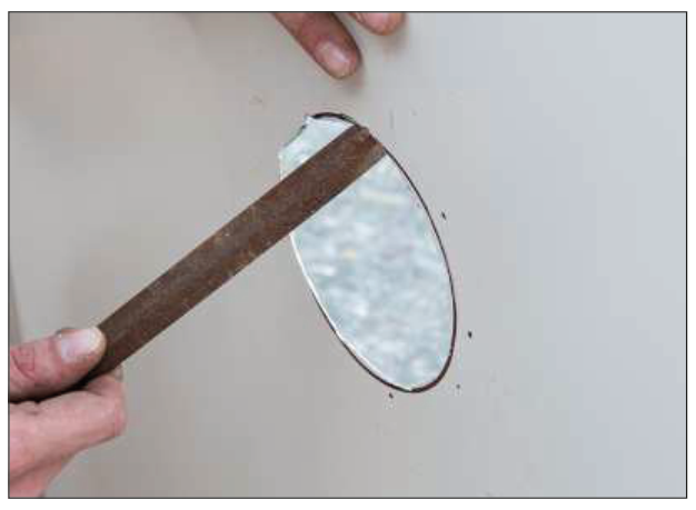
If the opening is pre-punched at the factory but not completely, carefully separate the inner metal piece with a suitable tool and remove the burrs from the edges.
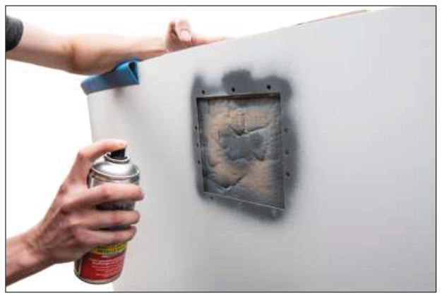
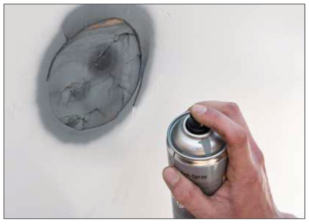
Whether the cut-out is made at the factory or on site, the edges must be treated with an anti-corrosion protector or plastic paint (see fig. 29).
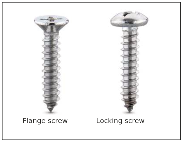
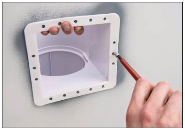
If the pipes are to be laid straight away, we recommend fitting the skimmer body now. To do so, slide the double skimmer seal onto the sheet-metal wall at the cut-out opening, press the skimmer against the opening from the outside and secure it from the inside with the smaller round-head fixing screws (see fig. 30). If 2 separate seals are included in the delivery, they are also fitted in the order seal – steel wall – seal.
Additional holes may need to be made in the steel wall (and treated with rust protection), as the holes for the fixing screws are not always already drilled.
If the pipes can be laid later, the skimmer can also be fitted only when the liner is installed (see section 4.7.2).
4.4.2Return inlets
Depending on the pool type, 2 return inlets are provided opposite the skimmer (on the opposite end of the pool) or 1 return inlet next to the skimmer (so the recessed fittings are all on one end). This is always stated in the scope of the order. On complete pools, or when the recessed fittings are ordered together with individual pools, the corresponding openings for the inlets are usually already cut out. If the opening is pre-punched at the factory but not completely, carefully separate the inner metal piece with a suitable tool and remove the burrs from the edges.
If the cut-outs are made on site, the openings for the inlets are made to the size of the inlet in the curve opposite the skimmer, using a drill and a jigsaw. Here too, remove the burrs from the edges.
The distance from the upper edge of the inlet opening to the upper edge of the pool should be about 30 cm, and the distance between the two inlets about 200 cm.
Whether the cut-out is made at the factory or on site, the edges must be treated with an anti-corrosion protector or plastic paint (see fig. 32).
4.4.2.1Return inlets for fixed pipe connection (for in-ground pools)
Very important for return inlets with fixed pipe connection: the inlet body must be fitted now, before the liner is installed, as these are special high-quality return inlets with a flange on the pool side, which makes a later liner replacement considerably easier than with standard inlets.
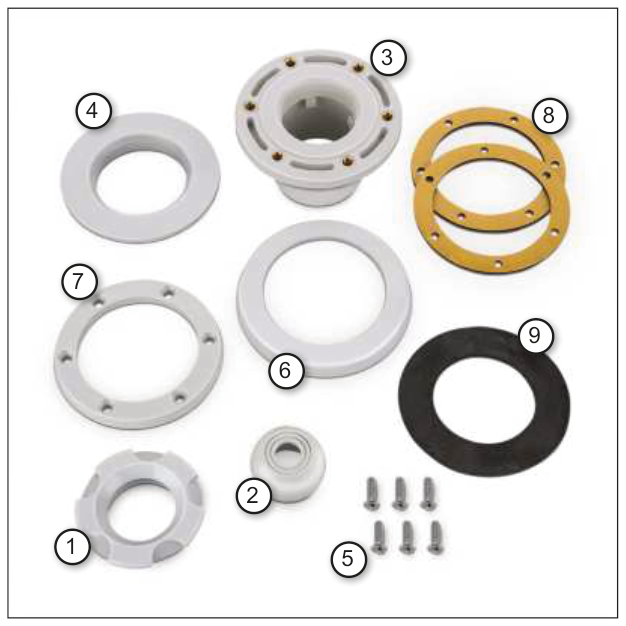
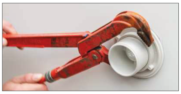
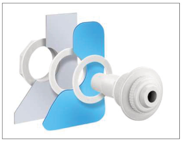
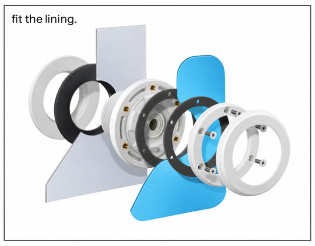
To do this, unscrew the lock nut at the back of the inlet and remove the cover plate, the flange (which is often sunk into the channel of the cover plate) and the 2 seals. At the front, remove the adjusting ring or the inlet eyeball.
Parts of the return inlet: 1) adjusting ring; 2) inlet eyeball; 3) inlet body; 4) lock nut; 5) screws; 6) cover plate; 7) flange; 8) seals (see fig. 33).
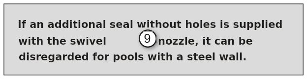
If an additional seal without holes is supplied with the return inlet, it is not needed on pools with a steel wall.
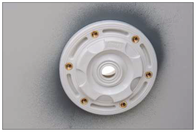
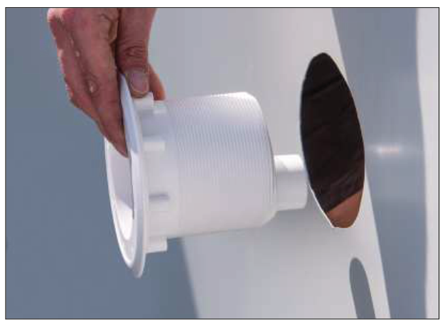
The inlet body is now inserted from the inside through the cut-out opening in the steel wall.
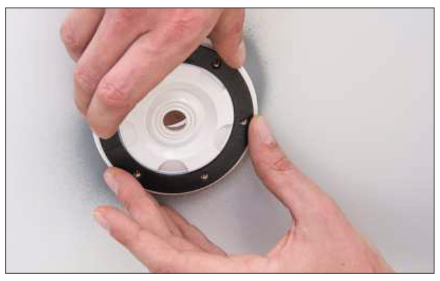
Now stick one of the two self-adhesive seals onto the flange frame of the inlet body.
Then screw the lock nut onto the thread of the inlet from behind (from outside the pool) and tighten it.
Remove the adjusting ring and the inner eyeball of the inlet before starting assembly. They are fitted again only after the liner has been installed, that is, after the inlet opening has been cut out.
Return inlets with hose connection 32/38 mm are fitted only together with the liner (see section 4.7.1).
4.4.4Compact pool light (optional)
The opening (Ø 121 mm) for the recessed niche must be marked on the steel cladding, drilled, cut out with a jigsaw and then treated with rust-protection paint or zinc spray.
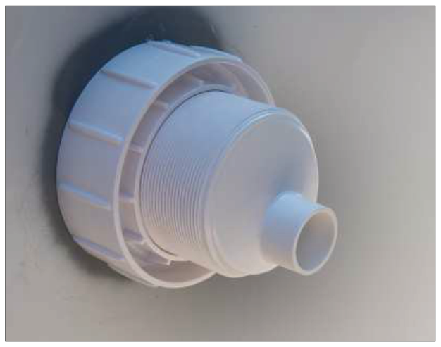
Then stick the seal without holes onto the back of the niche, pass the niche from the inside out through the opening and secure it from the outside with the lock nut. Make sure the lock nut is screwed onto the niche with the deep side facing forward.
Important: one of the gaskets with holes is now stuck on the inside onto the flange frame!
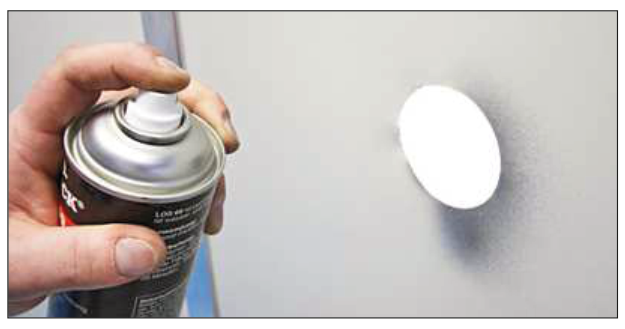
The edges of the resulting opening must be deburred and then treated with zinc spray or similar to prevent later corrosion of the steel wall (see fig. 40).
Once the adhesive seal without holes, included in the light kit, has been stuck onto the back of the niche, the niche can be placed in the opening from the inside out and secured from the outside with the lock nut. Make sure the lock nut is screwed onto the niche with the deep side facing forward (see fig. 42).
4.4.5Recessed counter-current system (optional)
The recessed counter-current system is positioned so that an inspection chamber with minimum dimensions of 100 × 100 × 100 cm can be provided behind it (bear in mind the possibility of draining the chamber!).
For the installation of the counter-current system, follow the installation instructions of the respective manufacturer. Naturally, here too the openings in the pool wall must be carefully protected against corrosion.
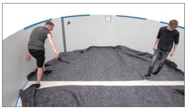
4.5Laying the underlay fleece
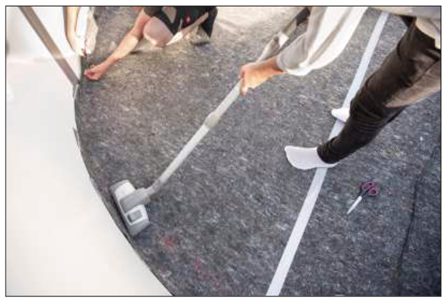
We recommend using a polyester underlay fleece or a protective floor cover (as a rule included in complete pool kits) to protect the inner liner from direct contact with the base and from any materials it may contain that are incompatible with PVC. However, the underlay fleece can only protect; it does not level out unevenness.
Before the fleece is laid out, the base must be thoroughly cleaned.
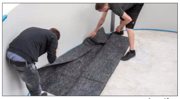
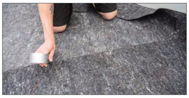
In some cases the fleece is already cut to the size of the pool. If it is delivered in rolls, lay it out in strips and fix it with adhesive tape.
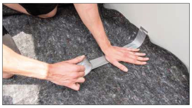
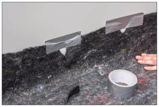
Cut the fleece about 10 cm larger than the size of the pool and let it extend upwards along the pool wall by about 5 cm all round. The offcut can be used for smaller end pieces. Pull the protruding part over the lower profiles and stick the fleece to the steel wall with strong adhesive tape.
Smooth out the underlay fleece and join it at the seams as well with strong adhesive tape. Then, every 20–25 cm, small wedges must be cut out of the fleece to remove excess material or to prevent the fleece from overlapping.
Any folds and wrinkles in the fleece disappear by themselves with the water pressure and over time.
4.6Hanging the inner liner and fitting the top edge
The inner liner must be installed at temperatures between +15 °C and +25 °C. Care must also be taken to maintain the stated minimum temperature overnight, as nights are still quite cold, especially in spring, and otherwise the inner liner will not “warm up” quickly enough when it is fitted, especially if it has been stored outdoors. Not in strong sunlight! At too high a temperature the liner is soft, elastic and too large. At too low a temperature the inner liner is hard, inelastic and too small (size differences of up to 50 cm!).
Clean the inside of the pool again.
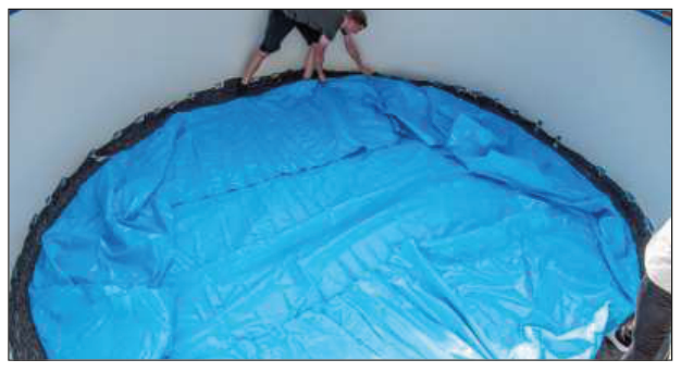
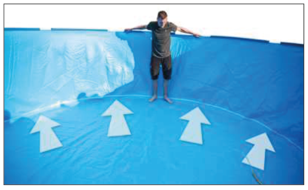
Now place the inner liner in the centre and spread it out so that the outer seams of the bottom are at an even distance from the steel wall, as the liner is always somewhat smaller than the pool itself.
Make sure the vertical weld is not located in the area of the skimmer, the return inlets or the lights, as otherwise watertightness is not guaranteed.
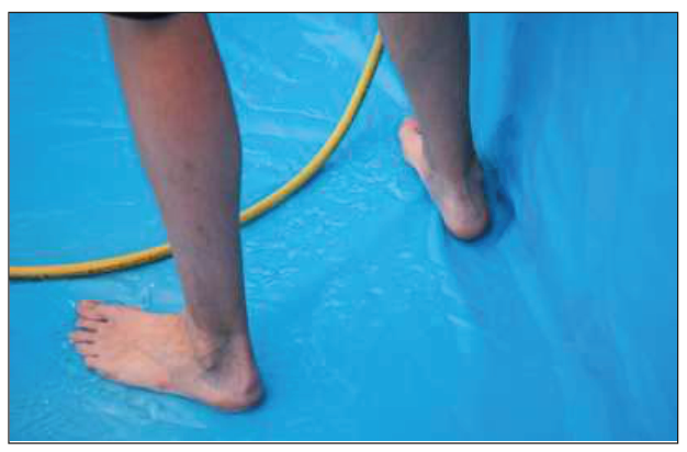
Step into the inner PVC liner only barefoot or with suitable footwear.
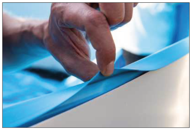
Regardless of the top edge, the inner liner always has a welded hook-in profile, the so-called hanging edge (see fig. 51).
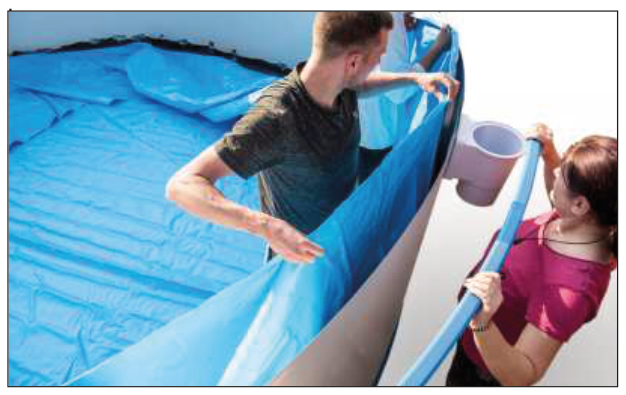
Slide the edge of the liner with the welded hook-in profile over the edge of the steel wall and secure the liner with several loose sections of the top edge (see fig. 52).
Only after the liner welds have been aligned evenly, fit the top edge completely (see section 4.6.1).
4.6.1Fitting the top edge (general)
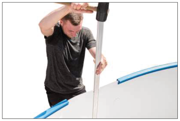
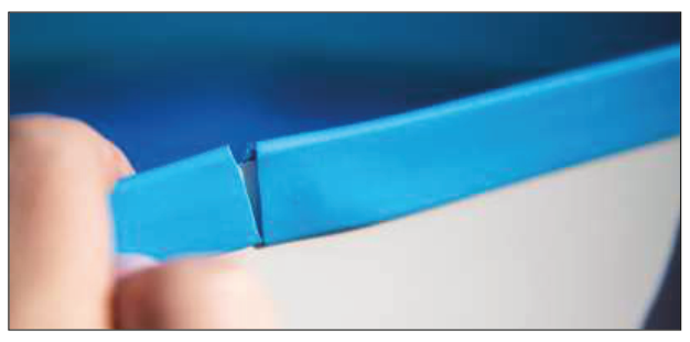
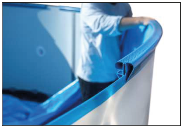
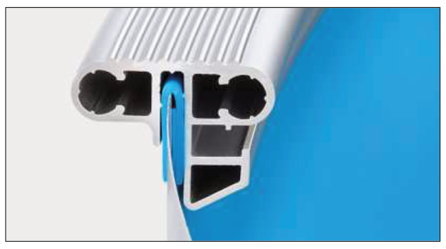
Join the sections of the top edge with the connecting pins; with blows from the palm of your hand or a rubber mallet, press them onto the pool edge so that the hook-in profile is engaged. If necessary, shorten one edge section (see fig. 55).
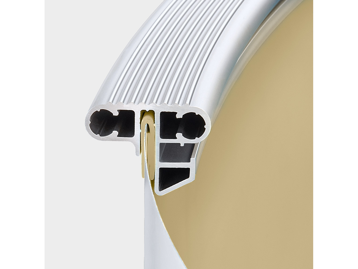
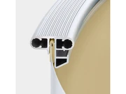
Additional notes for fitting the combined aluminium top edge:
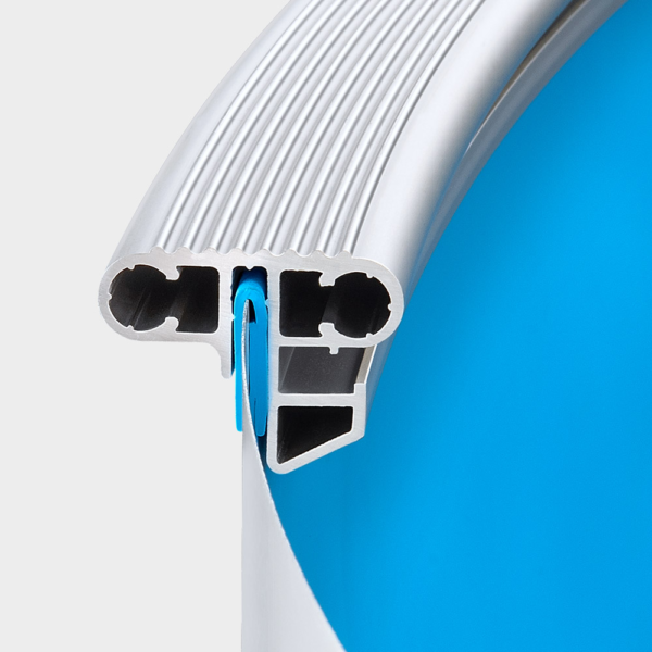
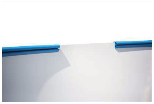
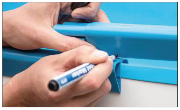
Assembly is basically identical to that of the plastic top edge. The profiles come already cut to the appropriate size for the pool from the factory. At the side posts the edge sections butt against the side posts. The edge is therefore not continuous but has 2 interruptions, which are later covered by the seating platforms. If necessary, or if there are dimensional deviations, the sections at these points can be mitred afterwards for an even better fit. A total of 2 plastic caps are included in the kit. When the pool is filled, it can happen that, owing to the expansion of the steel wall, a larger gap forms at one or another butt joint of the edge sections. Use the caps once the pool is finished to cover these points.
4.6.2Smoothing out wrinkles
Diagonal wrinkles that appear in the wall part of the liner can be smoothed out by shifting them while the top edge is partially fixed.
Push the wrinkles in the bottom outwards, towards the pool wall. Above all, make sure the liner weld between the bottom and the wall part sits exactly in the bottom/wall corner of the pool wall and the bottom. Before the pool is filled, the liner must have an even distance everywhere from the welds to the pool edge and, if possible, show no more wrinkles. Since the inner liner is made in a reduced size, that is, somewhat smaller than the pool size, to allow for expansion due to temperature and water pressure, it is absolutely important that the bottom welds are not aligned unevenly in terms of their distance from the pool wall.
After the final fitting of the top edge, any wrinkles that may remain in the bottom can be corrected by filling the pool with about 2–3 cm of water and pushing the wrinkles outwards.
If the wrinkles in the wall cannot be corrected: wait until the water level reaches 20–30 cm; if the problem still persists then, partially remove the top edge (step by step, in no case completely!) and shift the side liner a little to one side to reduce the wrinkles or, if possible, eliminate them. During this operation the inner liner must always be held sufficiently by the top edge to prevent the liner from sliding into the pool.
If none of this gives the desired result and the wrinkles are of an unacceptable size, the only option is to start again completely.
4.6.3Fitting the cover platform
Now fix the two cover platforms onto the vertical supports with 4 screws each. The platform must form a clean top finish of the support and cover the sharp edges.
The platform is not suitable as a diving board!
4.7Fitting the recessed fittings
When the water level is about 20 cm below the first recessed fitting, you can begin fitting the flanges. The following installation notes apply only to the recessed fittings supplied with the pool.
4.7.1Return inlets
For hose connection 32/38 mm:
When the inner liner is aligned, cut out the liner to fit the punched hole in the sheet (somewhat smaller than the opening in the steel wall). Then place a seal between the liner and the steel wall and pass the inlet with the second seal through the opening, so that there is a seal both in front of the liner and behind it. Then tighten the inlet with the lock nut on the outside of the pool.
If a double seal is included in the kit, separate it in half to obtain 2 individual seals.
For fixed pipe connection 50 mm:
When the inner liner is aligned, pre-drill the holes for the screws, e.g. with an awl. Stick the 2nd seal behind the flange so that the seal sits between the liner and the flange. Tighten the flange screws crosswise.
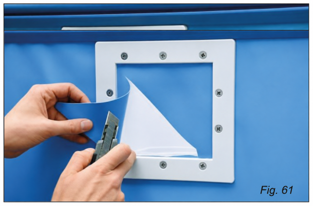
Then cut out the liner according to the opening. After that, tighten the ball and the adjusting ring again and fit the cover plate.
4.7.2Skimmer (surface suction unit)
Drill the holes for the screws, tighten the flange crosswise with screws, then cut out the skimmer opening and fit the cover plate. On the flange and the cover plate, the “Top” marking usually indicates the upper side. Fit the skimmer flap and the basket with strainer.
If the skimmer body is only fitted now together with the liner, place the double seal on the cut-out opening in the steel wall, hold the body from the outside, drill the holes for the screws from the inside and tighten the flange crosswise.
5Backfilling with lean concrete for in-ground or partially in-ground figure-of-eight pools
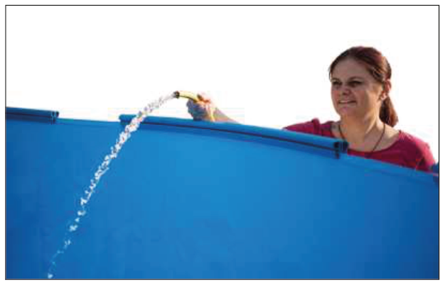
Fill the assembled and fully installed pool with water (initial height for pools 1.50 m deep, about 60 cm). Pools of 1.20 m or 1.35 m can be filled completely.
Before backfilling, place construction sheeting and polystyrene boards (thickness 15–25 mm) to protect the outer face of the steel wall in the rounded areas in the ground.
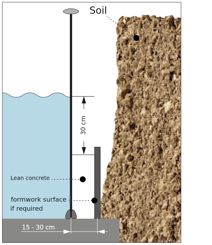
Backfill behind the pool wall in several layers (each 50 cm at most) with C8/10 lean concrete (or a mixing ratio of approximately 1:10 depending on the grain size of the gravel) of semi-dry consistency. The lower layer must have hardened before the next one is applied. With formwork boards or similar, the individual layers of lean concrete can be limited at the sides. After hardening, the formwork boards are moved upwards to shape the next layer (see fig. 63).
The concrete must not be too wet and must not be vibrated or tamped.
In natural soils (e.g. cohesive clay), the concrete backfill must be at least 15 cm thick. In soils that push, we recommend a backfill of about 30 cm.
During backfilling, the water level must always be about 30 cm higher than the outer concrete backfill.
When backfilling with concrete, make sure the pool wall is not deformed by the pressure of the concrete.
Likewise, excessive concrete pressure on the recessed skimmer must be avoided, as this can lead, among other things, to deformation and, later, to jamming of the skimmer flap. We recommend placing polystyrene or similar around the skimmer to absorb the concrete pressure at that point. Any damage to the steel wall must also be avoided, as it can lead to later corrosion and loss of the manufacturer's warranty. If scratches or other damage appear on the steel wall, they must be treated immediately with rust-protection products.
6.1Water level and skimmer flap
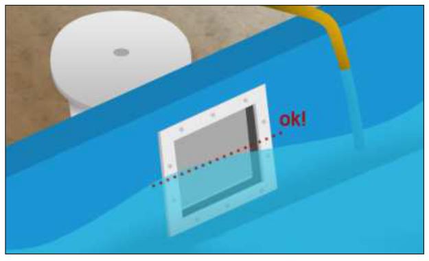
The water level in the pool must be adjusted to the skimmer opening. The optimum is from the middle up to 2/3 of the skimmer opening (see fig. 64). A water level that is too low must be avoided in any case, as it can cause damage to the pump. Both the free movement of the skimmer flap and the correct position of the skimmer basket must always be ensured, as otherwise both can impede the flow of water.
The suction plate should be in place only while cleaning the bottom and when using the bottom hose.
6.2Ladder for getting into the pool
Every pool needs a suitable means of access, which a pool ladder provides. Ladders for in-ground pools (partially or fully in-ground) differ from those for above-ground pools (partially or fully free-standing) as follows:
6.2.1Ladder for above-ground pools
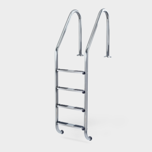
For free-standing or partially in-ground pools we recommend a ladder for above-ground pools (see fig. 65 and 66). If necessary (for partially in-ground pools), it can be adapted to the installation conditions by shortening the two outer tubes with a clean hacksaw or similar. The cuts must then be cleaned and the burrs removed. The adjustable step plates are then inserted into the ladder tubes.
6.2.2Ladder for in-ground pools
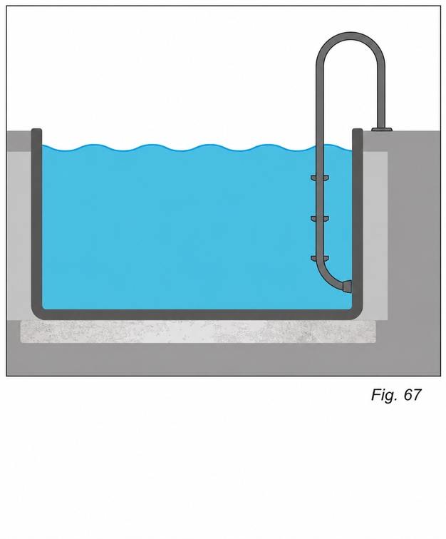
On the stainless steel ladder for in-ground pools there are two fixing options; different ladders are included with the kits; see the description of the respective kit (see fig. 67).
Plastic recessed sleeves: here the ladder must be fitted first. The recessed sleeves are then inserted into the ladder tubes and the ladder is placed at the desired position so that the ladder stops sit snug against the liner. The recessed sleeves are then cemented in (as regards the height of the recessed sleeves, think of the possible finishes of the pool edge).
Plug-in flanges for the ladder: here it is enough to concrete an area of about 100 × 50 cm around the intended fixing point at the desired position of the ladder. Take into account the overhang of the ladder according to the ladder type. The surrounding tiles are then fixed onto the concrete with mortar and the plug-in flanges of the ladder are screwed on top of them again. The ladder can then be fitted and inserted into the plug-in flanges.
Follow the enclosed installation instructions of the respective ladder.
Important! When fitting a pool ladder, be sure to use clean tools. Most of the tubes and steps of pool ladders are made of stainless steel, which can rust, for example through contact corrosion (on contact with so-called “base metals” or with tools). Therefore, when working with (“stainless”) steel, make sure to use the correct tool. Do not use tools that already show rust corrosion on the surface or similar, or that have been used to fit parts made of “normal” steel. For this reason it is recommended to use a separate tool for working with stainless steel and for working with other metals.
6.3Repairing the pool liner
Damage to the inner liner of the pool can be repaired without difficulty with a repair kit.
6.4Maintenance and care
The combination of mechanical water filtration and chemical water treatment ensures that the water is always clean and clear.
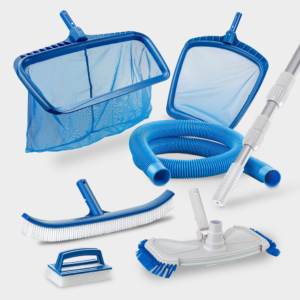
Mechanical water filtration: the smallest dirt particles on the surface (e.g. pollen, grass, hair) are drawn off by the skimmer and the filtration system. Coarse dirt (leaves, insects) is removed with a leaf skimmer and/or a pool cleaner.
Chemical water treatment: manual cleaning of the bottom (vacuuming) presupposes a filtration system and a skimmer/surface skimmer. Before manual cleaning, the sand filter must first be properly backwashed and rinsed.
Manual vacuuming of the bottom: the skimmer kit usually includes the so-called “suction plate”, which, together with a cleaning brush (vacuum brush), possibly with a telescopic pole, and a suction hose (connection of the brush to the suction plate), is also required. To vacuum coarse dirt, the suction hose is inserted into the connector of the suction plate and the plate is placed on the skimmer basket. The hose and the telescopic pole are then connected to the pool cleaner, the sand filter valve for bottom cleaning is set to the “Filtration” position and cleaning can begin.
Make sure the suction hose is completely filled with water so that the pool pump does not draw in air.
Professional tip for bleeding air from the hose: to bleed the suction hose completely for manual cleaning, you can briefly bring it close to the return inlet with the filtration system running. The movement of the water forces all the air out of the hose; when no more air bubbles come out of the other end of the hose, or out of the vacuum brush, it is completely bled and the filtration system can be switched off.
Fit the suction plate on the skimmer, insert the hose into the suction plate and switch the sand filter on again. If air nevertheless enters the filtration system, you must switch off the pool pump and bleed the pool cleaner again; the filtration system, as a rule, bleeds itself. To vacuum, move the brush slowly and evenly over the bottom of the pool (moving too fast can stir up the dirt). For sand filters without a pre-filter, a skimmer with a basket is essential.
If the filtration performance decreases, the causes may be the following:
- The filter sand is dirty: backwash the filter.
- The pump draws in air (air bubbles on the discharge side): faulty hoses, check the clamps.
- The skimmer receives too little water: check the water level and raise it if necessary.
- The skimmer basket is dirty: clean it.
- The strainer basket of the filter pump is dirty: clean it.
6.5Winterising
All in-ground pools must stay partially filled with water during winter to balance the external pressure.
First the pH value must be adjusted to 7.0 and any cloudiness of the water or algae growth eliminated with shock chlorination.
Then the water level should be lowered to about 10 cm below the return inlets and the pipes and the filtration system (water and quartz sand) drained. The return inlets can be closed with winterising plugs.
If the pool has built-in lights, the water level must be below or above them.
After lowering the level, add a winter protection product to the water. To prevent ice pressure on the pool walls, it is recommended to place ice-pressure cushions.
6.6Safety notes
General precautions:
Never let children play unsupervised in or near the pool; explain the possible dangers to them. Teach children to swim if necessary. Cover the pool when it is not in use. After eating or sunbathing, get into the water very slowly. Risk of cardiovascular failure or cardiac arrest!
Immediate help in the event of an accident while bathing:
Get those affected out immediately. Check the pulse and breathing. If necessary, immediately give mouth-to-mouth resuscitation and cardiac massage. Call the emergency services.
Technical safety notes:
Read all the information carefully before using the pool and ask if anything is unclear. Follow the recommendations. They are for your safety and that of the pool users. Keep this document carefully so that you can use it again later.
The typical risks of using the pool are described below, without any claim to being exhaustive. Not every danger in every possible individual case is covered. Therefore, use common sense in all activities around and in the pool.
Safety of non-swimmers:
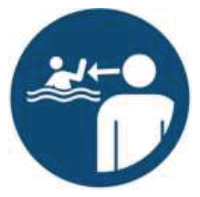
- At all times make sure that non-swimmers and users with limited swimming ability, especially small children, are supervised by a person who can, if necessary, rescue them and call for help.
- To avoid misunderstandings in communication: appoint a person able to help who constantly watches the pool during use.
- Non-swimmers and people with limited swimming ability must wear personal protective equipment (inflatable armbands, etc.) when using the pool.
- Remove toys from the pool and its surroundings when the pool is not in use or not supervised. This prevents children from being attracted to them.
Safe access to the pool:
If the access device (ladder) cannot be lifted or folded, and to prevent unexpected access to the pool by children and drowning, we recommend securing the access to the pool with a protective device.
Safety devices:
Safety devices can not only prevent unexpected access to the pool by children and thus avoid drowning. They also protect in general against unauthorised access to the pool. For this reason we recommend not doing without additional safety measures. Depending on individual circumstances, this could be, for example, a fence, a cover with special accident protection, a roof enclosure or an alarm system.
In addition, we recommend securing the doors and windows of your house, as well as access to the property, to prevent unauthorised access to the pool.
Protective accessories can make the pool safer, but they never replace permanent supervision of children by an adult who can help if necessary.
Safety equipment:
- We recommend keeping rescue equipment (for example, a lifebuoy) near the pool.
- Make sure there is a working telephone and a list of emergency telephone numbers near the pool, so that you can call for help quickly in an extraordinary situation.
Safe use of the pool:
- Encourage all users of the pool, especially children, to learn to swim.
- Learn first-aid measures (cardiopulmonary resuscitation) and refresh what you have learned regularly. In an extraordinary situation it can make a life-saving difference.
- Explain to all users, including children, before using the pool what to do in an extraordinary situation.
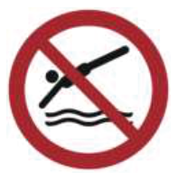
- Never jump into shallow water. This can cause serious injury or death.
- Do not use the pool if you are under the influence of alcohol or of medication that may affect your ability to use the pool safely.
- If the pool is equipped with a cover: before using the pool, make sure that the cover is fully open or fully removed from the water surface.
- To protect pool users from waterborne diseases, make sure the water is always treated and hygienically safe. To do this, follow the instructions and the information on water treatment.
- Keep chemicals and water-care products (for example, products for water treatment, cleaning or disinfection) out of the reach of children.
- Removable ladders must be placed on a level surface.
Put up the following safety signs in a clearly visible place, less than 2 metres from the pool:







 Ibiza 0 DL 5.25 × 3.20 m – with assembly →

 RO
 EL
 RU
 BG
 MK